
Tour:
A Pictorial Chronology of the Rebuilding of a Model "A" Ford Engine
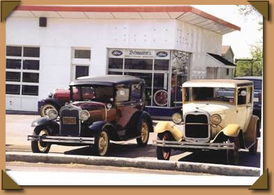
"Welcome
to our new shop!"
 Step
#1
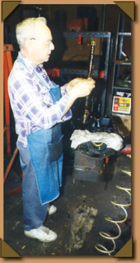
Engines are disassembled
in the "dirty room" and each part is checked with a micrometer for acceptable
tolerances by Harry (who owns a '29 "A" Sport Coupe). Ora's father,
Ira, also assists.
 Step
#2
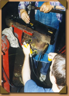
Continuing with
the disassembly process, the engine block is Magnafluxed, a process
that searches for engine block cracks from freezing or metal fatigue.
 Step
#3
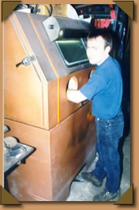
All parts are thoroughly
cleaned (not shown), then bead blasted to remove remaining paint and
dirt, and immediately labeled to ensure that a customer's parts stay
with the proper engine block.
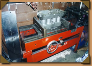 Step
#4
The engine block
is next brought to the shop for "deck resurfacing" (the surface where
the head attaches to the engine block is milled perfectly flat). The
cylinder head and manifold assembly are also done in the same manner
(not shown).
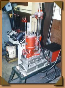 Step
#5
The cylinders are machined by a boring bar to the next oversize diameter piston size available. If the maximum bore (diameter) has been reached, the cylinders are sleeved, returning the bore to the original (standard) diameter.
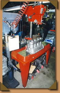 Step
#6
The valve seats
of the deck surface are bored to install hardened valve seats.
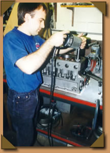 Step
#7
As shown by Ora,
the new valve seats are installed and ground with three angled surfaces
- 60,45, and 30 degrees.
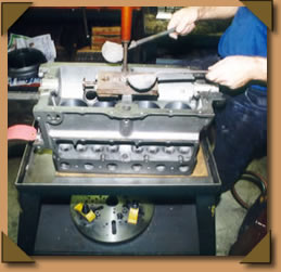 Step
#8
The engine block
is inverted. A "fixturing mold" is placed on each half of a bearing
surface and molten Babbitt is poured in the mold, creating a new bearing
surface.
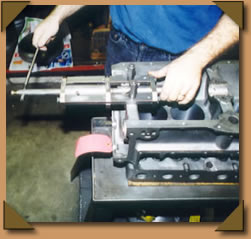 Step
#9
Oil grooves are
cut in the new Babbitt (bearing surface) with a special cutter.
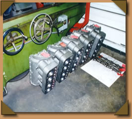 Step
#10
A few of the engine
blocks and cam shafts under re-manufacturing - note the red identification
tags on all parts.
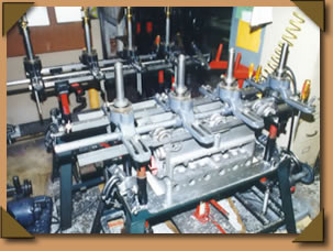 Step
#11
The roughly poured
main bearings are line bored to accept the machined surface of the crankshaft
- each half of the main bearing cap is laid aside in the picture to
allow a full view of the boring bar.
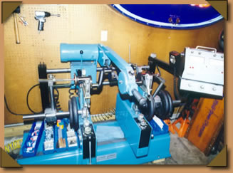 Step
#12
An optional process for standard crankshafts, the crankshaft, flywheel and pressure plate are spun dynamically to measure their balance coordinates. Imbalances are removed. (Note: this process is mandatory for counterweighted crankshafts. See step #13.)
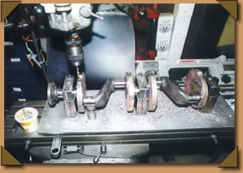 Step
#13
Counter weights are added to the crankshaft. Theoretically, it prolongs the engine life, and the engine runs smoother. Typically, this is done in conjunction with the lightening of the flywheel and the use of a modern V8 pressure plate.
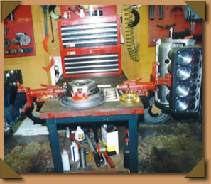 Step
#14
The cylinder walls
are honed to size to accept the new pistons and rings; and the block
receives a final cleaning (not shown). The engines are placed on bench-mounted
stands for final assembly - all parts have been painted as required,
for each engine, by Jan when this stage is reached.
***********************************************
Additional processes normally performed on an engine, but not shown,
include crankshaft journals regrinding, connecting rods reconditioning,
cam lobes regrinding, flywheel and pressure plate balancing (see pictures
#12 and #13 for the balancing of crankshafts), balancing of pistons
and connecting rods, and reconditioning and balancing of flywheel and
pressure plate.
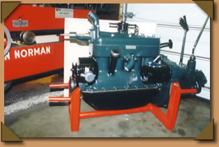 Step
#15
This is an example of a completed engine and transmission that has gone through the 2 to 3 month rebuilding process.
Fini!!!